April 21, 2015

ACI for (Smarter) Simple Minds


In a previous post I tried to describe the new Cisco ACI architecture in simple terms, from a software designer standpoint.
My knowledge on networking is limited, compared to my colleagues at Cisco that hold CCIE certifications… I am a software guy the just understands the API   ;-)
Though, now I would like to share some more technical information with the same “not for specialists” language.
You can still go to the official documentation for the detail, or look at one of the brilliant demo recorded on YouTube.

These are the main points that I want to describe:
- You don’t program the single switches, but the entire fabric (via the sw controller)
- The fabric has all active links (no spanning tree)
- Policies and performances benefit from a ASIC design that perfectly fits the SDN model
- You can manage the infrastructure as code (hence, really do DevOps)
- The APIC controller manages also L4-7 network services from 3rd parties
- Any orchestrator can drive the API of the controller
- The virtual leaf of the fabric extends into the hypervisor (AVS)
- You get immediate visibility of the Health Score for the Fabric, Tenants, Applications

Next picture shows how the fabric is build, using two types of switches: the Spines are used to scale and connect all the leaves in a non blocking fabric that ensures performances and reliability.
The Leaf switches hold the physical ports where servers are attached: both bare metal servers (i.e. running a Operating System) and virtualized servers (i.e. running ESXi, Hyper-V and KVM hypervisors).
The software controller for the fabric, named APIC, runs on a cluster of (at least) 3 dedicated physical servers and is not in the data path: so it does not affect performances and reliability of the fabric, as it could happen with other solutions on the market.

The ACI fabric supports more than 64,000 dedicated tenant networks. A single fabric can support more than one million IPv4/IPv6 endpoints, more than 64,000 tenants, and more than 200,000 10G ports. The ACI fabric enables any service (physical or virtual) anywhere with no need for additional software or hardware gateways to connect between the physical and virtual services and normalizes encapsulations for Virtual Extensible Local Area Network (VXLAN) / VLAN / Network Virtualization using Generic Routing Encapsulation (NVGRE).

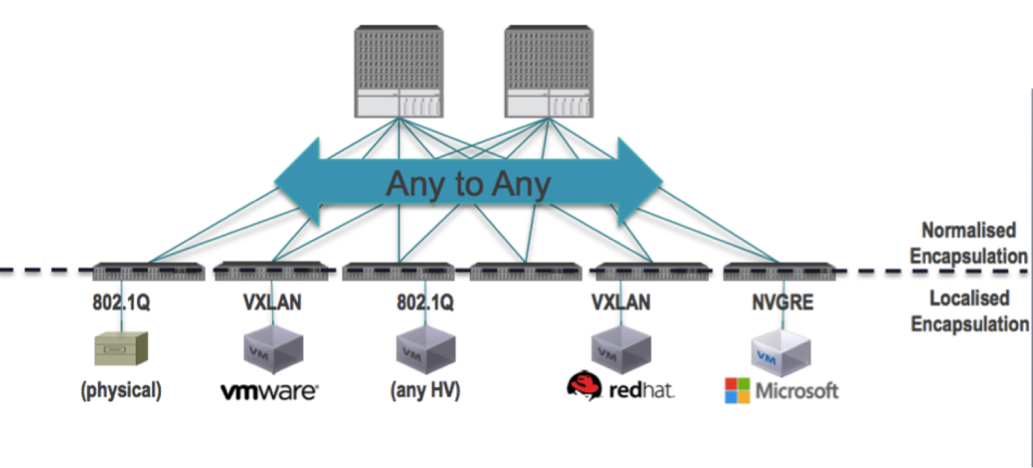
The ACI fabric decouples the endpoint identity and associated policy from the underlying forwarding graph. It provides a distributed Layer 3 gateway that ensures optimal Layer 3 and Layer 2 forwarding. The fabric supports standard bridging and routing semantics without standard location constraints (any IP address anywhere), and removes flooding requirements for the IP control plane Address Resolution Protocol (ARP) / Generic Attribute Registration Protocol (GARP). All traffic within the fabric is encapsulated within VXLAN.

The ACI fabric decouples the tenant endpoint address, its identifier, from the location of the endpoint that is defined by its locator or VXLAN tunnel endpoint (VTEP) address. The following figure shows decoupled identity and location.


Forwarding within the fabric is between VTEPs. The mapping of the internal tenant MAC or IP address to a location is performed by the VTEP using a distributed mapping database. After a lookup is done, the VTEP sends the original data packet encapsulated in VXLAN with the Destination Address (DA) of the VTEP on the destination leaf. The packet is then de-encapsulated on the destination leaf and sent down to the receiving host. With this model, we can have a full mesh, loop-free topology without the need to use the spanning-tree protocol to prevent loops.

You can attach virtual servers or physical servers that use any network virtualization protocol to the Leaf ports, then design the policies that define the traffic flow among them regardless the local (to the server or to its hypervisor) encapsulation.
So the fabric acts as a normalizer for the encapsulation and allows you to match different environments in a single policy.

Forwarding is not limited to nor constrained by the encapsulation type or encapsulation-specific ‘overlay’ network:


As explained in ACI for Dummies, policies are based on the concept of EPG (End Points Group).
Special EPG represent the outside network (outside the fabric, that means other networks in your datacenter or eventually the Internet or a MPLS connection):


The integration with the hypervisors is made through a bidirectional connection between the APIC controller and the element manager of the virtualization platform (vCenter, System Center VMM, Red Hat EVM...). Their API are used to create local virtual networks that are connected and integrated with the ACI fabric, so that policies are propagated to them.
The ultimate result is the creation of Port Groups, or the like of, where VM can be connected.
A Port Groups represents a EPG.
Events generated by the VM lifecycle (power on/off, vmotion...) will be sent back to APIC so that the traffic is managed accordingly.


How Policies are enforced in the fabric

The policy contains a source EPG, a destination EPG and rules known as Contracts, made of Subjects (security, QoS...). They are created in the Controller and pushed to all the leaf switches where they are enforced.
When a packet arrives to a leaf, if the destination EPG is known it is processed locally.
Otherwise it is forwarded to a Spine, to reach the destination EPG through a Leaf that knows it.

There are 3 cases, and the local and global tables in the leaf are used based on the fact that the destination EP is known or not:
1 - If the target EP is known and it's local (local table) to the same leaf, it's processed locally (no traffic through the Spine).
2 - If the target EP is known and it's remote (global table) it's forwarded to the Spine to be sent to the destination VTEP, that is known.
3 - If the target EP is unknown the traffic is sent to the Spine for a proxy forwarding (that means that the Spine discovers what is the destination VTEP).


You can manage the infrastructure as code.

The fabric is stateless: this means that all the configuration/behavior can be pushed to the network through the controller's API. The definition of Contracts and EPG, of POD and Tenants, every Application Profile is a (set of) XML document that can be saved as text.
Hence you can save it in the same repository as the source code of your software applications.

You can extend the DevOps pipeline that builds the application, deploys it and tests it automatically by adding a build of the required infrastructure on demand.
This means that you can use a slice of a shared infrastructure to create a environment just when it's needed and destroy it soon after, returning the resources to the pool.

You can also use this approach for Disaster Recovery, simply building a clone of the main DC if it's lost.

Any orchestrator can drive the API of the controller.

The XML (or JSON) content that you send to build the environment and the policies is based on a standard language. The API are well documented and lot of samples are available.
You can practice with the API, learn how to use them with any REST client and then copy the same calls into your preferred orchestrator.
Though some products have out of the box native integration with APIC (Cisco UCSD, Microsoft), any other can be used easily with the approach I described above.
See an example in The Elastic Cloud Project.

The APIC controller manages also L4-7 network services from 3rd parties. 

The concept of Service Graph allows a automated and scalable L4-L7 service insertion.  The fabric forwards the traffic into a Service Graph, that can be one or more service nodes pre-defined in a series, based on a routing rule.  Using the service graph simplifies and scales service operation: the following pictures show the difference from a traditional management of the network services.


The same result can be achieved with the insertion of a Service Graph in the contract between two EPG:


The virtual leaf of the fabric extends into the hypervisor (AVS).

Compared to other hypervisor-based virtual switches, AVS provides cross-consistency in features, management, and control through Application Policy Infrastructure Controller (APIC), rather than through hypervisor-specific management stations. As a key component of the overall ACI framework, AVS allows for intelligent policy enforcement and optimal traffic steering for virtual applications.

The AVS offers:
  • Single point of management and control for both physical and virtual workloads and infrastructure
  • Optimal traffic steering to application services
  • Seamless workload mobility
  • Support for all leading hypervisors with a consistent operational model across implementations for simplified operations in heterogeneous data centers


Cisco AVS is compatible with any upstream physical access layer switch that complies with the Ethernet standard, including Cisco Nexus Family switches. Cisco AVS is compatible with any server hardware listed in the VMware Hardware Compatibility List (HCL). Cisco AVS is a distributed virtual switch solution that is fully integrated into the VMware virtual infrastructure, including VMware vCenter for the virtualization administrator. This solution allows the network administrator to configure virtual switches and port groups to establish a consistent data center network policy.

Next picture shows a topology that includes Cisco AVS with Cisco APIC and VMware vCenter with the Cisco Virtual Switch Update Manager (VSUM).


Health Score

The APIC uses a policy model to combine data into a health score. Health scores can be aggregated for a variety of areas such as for infrastructure, applications, or services.

The APIC supports the following health score types:
      System—Summarizes the health of the entire network.
      Leaf—Summarizes the health of leaf switches in the network. Leaf health includes hardware health of the switch including fan tray, power supply, and CPU.
      Tenant—Summarizes the health of a tenant and the tenant’s applications.


Health scores allow you to isolate performance issues by drilling down through the network hierarchy to isolate faults to specific managed objects (MOs). You can view network health by viewing the health of an application (by tenant) or by the health of a leaf switch (by pod).


You can subscribe to a health score to receive notifications if the health score crosses a threshold value. You can receive health score events via SNMP, email, syslog, and Cisco Call Home.  This can be particularly useful for integration with 3rd party monitoring tools. 

Health Score Use case: 
An application administrator could subscribe to the health score of their application - and receive automatic notifications from ACI if the health of the specific application is degraded from an infrastructure point of view - truly an application-aware infrastructure.


Conclusion

I hope that these few lines were enough to show the advantage that modern network architectures can bring to your Data Center.
Cisco ACI joins all the benefit of the SDN and the overlay networks with a powerful integration with the hardware fabric, so you get flexibility without losing control, visibility and performances.

One of the most important aspects is the normalization of the encapsulation, so that you can merge different network technologies (from heterogeneous virtual environments and bare metal) into a single well managed policy model.

Policies (specifically, the Application Network Policies created in APIC based on EPG and Contracts) allow a easier communication between software application designers and infrastructure managers, because they are simple to represent, create/maintain and enforce.

Now all you need is just a look at ACI Fundamentals on the Cisco web site.


April 8, 2015

Software Defined Networking For Dummies


A very simple, yet complete description of what SDN is, now available as a free ebook that you can download from http://www.cisco.com/go/sdnfordummies


Software defined networking (SDN) is a new way of looking at how networking and cloud solutions should be automated, efficient, and scalable in a new world where application services may be provided locally, by the data center, or even the cloud. This is impossible with a rigid system that’s difficult to manage, maintain, and upgrade. Going forward, you need flexibility, simplicity, and the ability to quickly grow to meet changing IT and business needs.

Software Defined Networking For Dummies, Cisco Special Edition, shows you what SDN is, how it works, and how you can choose the right SDN solution. This book also helps you understand the terminology, jargon, and acronyms that are such a part of defining SDN.
Along the way, you’ll see some examples of the current state of the art in SDN technology and see how SDN can help your organization. 


You can find additional information about Cisco’s take on SDN by visiting:
http://cisco.com/go/aci
http://cisco.com/go/sdn
http://blogs.cisco.com/tag/sdn

March 25, 2015

Invoking UCS Director Workflows via the Northbound REST API


This is a guest post, offered by a colleague of mine: Russ Whitear.
Russ is the UCS Director guru  in our team and, when I saw an internal email where he explained how to use the UCS Director API from an external client, I asked his permission to publish it.
I believe it will be useful for many customers and partners to integrate UCSD in a broader ecosystem.

This short post explains how to invoke UCS Director workflows via the northbound REST API. Authentication and role is controlled by the use of a secure token.  Each user account within UCS Director has a unique API token, which can accessed via the GUI like so:

Firstly, from within the UCS Director GUI, click the current username at the top right of the screen. Like so:


User Information will then be presented. Select the ‘Advanced’ tab in order to reveal the API Access token for that user account.


Once retrieved, this token needs to be added as an HTTP header for all REST requests to UCS Director.  The HTTP header name must be X-Cloupia-Request-Key.
X-Cloupia-Request-Key : E0BEA013C6D4418C9E8B03805156E8BB


Once this step is complete, the next requirement is to construct an appropriate URI for the HTTP request in order to invoke the required UCS Director workflow also supplying the required User Inputs (Inputs that would ordinarily be entered by the end user when executing the workflow manually).

UCS Director has two versions of northbound API. Version 1 uses HTTP GET requests with a JSON (Java Standard Object Notation) formatted URI. Version 2 uses HTTP POST with XML (eXtensible Markup Language) bodytext.

Workflow invokation for UCS Director uses Version 1 of the API (JSON). A typical request URL would look similar to this:

http://<UCSD_IP>/app/api/rest?formatType=json
                 &opName=userAPISubmitWorkflowServiceRequest
                 &opData={SOME_JSON_DATA_HERE}

A very quick JSON refresher

JSON formatted data consists of either dictionaries or lists. Dictionaries consist of name/value pairs that are separated by a colon. Name/value pairs are separated by a comman and dictionaries are bounded by curly braces. For example:

{“animal”:”dog”, “mineral”:”rock”, “vegetable”:”carrot”}

Lists are used in instances where a single value is insufficient. Lists are comma separated and bounded by square braces. For example:

{“animals”:[“dog”,”cat”,”horse”]}

To ease readability, it is often worth temporarily expanding the structure to see what is going on. 

{
    “animals”:[
        “dog”,
        ”cat”,
        ”horse”
    ]
}

Now things get interesting. It is possible (And common) for dictionaries to contain lists, and for those lists to contain dictionaries rather than just elements (dog, cat, horse etc…). 

{ “all_things”:{
        “animals”:[
            “dog”,
            ”cat”,
            ”horse”
        ],
        “minerals”:[
            “Quartz”,
            “Calcite”
        ],
        “vegetable”:”carrot”
    }
}


With an understanding of how JSON objects are structured, we can now look at the required formatting of the URI for UCS Director. When invoking a workflow via the REST API, UCS Director must be called with three parameters, param0, param1 and param2. ‘param0’ contains the name of the workflow to be invoked. The syntax of the workflow name must match EXACTLY the name of the actual workflow. ‘param1’ contains a dictionary, which itself contains a list of dictionaries detailing each user input and value that should be inserted for that user input (As though an end user had invoked the workflow via the GUI and had entered values manually.

The structure of the UCS Director JSON URI looks like so:


{
    param0:"<WORKFLOW_NAME>",
    param1:{
                "list":[
                       {“name":"<INPUT_1>","value":"<INPUT_VALUE>"},
                       {"name":"<INPUT_2>","value":"<INPUT_VALUE"}
                ]
            },
    param2:-1
}


So, let’s see this in action. Take the following workflow, which happens to be named ‘Infoblox Register New Host’ and has the user inputs ‘Infoblox IP:’,’Infoblox Username:’,’Infoblox Password:’,’Hostname:’,’Domain:’ and ‘Network Range:’.


The correct JSON object (Shown here in pretty form) would look like so:


Note once more, that the syntax of the input names must match EXACTLY that of the actual workflow inputs.

After removing all of the readability formatting, the full URL required in order to invoke this workflow with the ‘user’ inputs as shown above would look like this:


Now that we have our URL and authentication token HTTP header, we can simply enter this information into a web based REST client (e.g. RESTclient for Firefox or Postman for Chrome) and execute the request. Like so:


If the request is successful, then UCS Director will respond with a “serviceError” of null (No error) and the serviceResult will contain the service request ID for the newly invoked workflow:


Progress of the workflow can either be monitored by other API requests or via the UCS Director GUI:


Service request logging can also be monitored via either further API calls or via the UCS Director GUI:


This concludes the example, that you could easily test on your own instance of UCS Director or, if you don't have one at hand, in a demo lab on dcloud.cisco.com.

It should be enough to demonstrate how simple is the integration of the automation engine provided by UCSD, if you want to execute its workflows from an external system: a front end portal, another orchestrator, your custom scripts.

See also The Elastic Cloud project - Porting to UCSD for the deployment of a 3 tier application to 3 different hypervisors, using Openstack and ACI with Cisco UCS Director.


March 17, 2015

The Elastic Cloud project - Porting to UCSD

Porting to a new platform

This post shows how we did the porting of the Elastic Cloud project to a different platform.
The initial implementation was done on Cisco IAC (Intelligent Automation for Cloud) orchestrating Openstack, Cisco ACI (Application Centric Infrastructure) and 3 hypervisors.

Later we decided to implement the same use case (deploy a 3 tier application to 3 different hypervisors, using Openstack and ACI) with Cisco UCS Director, aka UCSD.

The objective was to offer another demonstration of flexibility and openness, targeting IT administrators rather than end users like we did in the first project.
You will find a brief description of UCS Director in the following paragraphs: essentially it is not used to abstract complexity, but to allow IT professionals to do their job faster and error-proof.
UCSD is also a key element in a new Cisco end-to-end architecture for cloud computing, named Cisco ONE Enterprise Cloud suite.

The implementation was supported by the Cisco dCloud team, the organization that provides excellent remote demo capabilities on a number of Cisco technologies. They offered me the lab environment to build the new demo and, in turn, the complete demo will be offered publicly as a self service environment on the dCloud platform.

The dCloud demo environment

Cisco dCloud provides Customers, Partners and Cisco Employees with a way to experience Cisco Solutions. From scripted, repeatable demos to fully customizable labs with complete administrative access, Cisco dCloud can work for you. Just login to dcloud.cisco.com with your Cisco account and you'll find all the available demo:


Cisco UCS Director

UCSD is a great tool for Data Center automation: it manages servers, network, storage and hypervisors, providing you a consistent view on physical and virtual resources in your DC.

Despite the name (that could associate it to Cisco UCS servers only) it integrates with a multi-vendor heterogeneous infrastructure, offering a single dashboard plus the automation engine (with a library containing 1300+ tasks) and the SDK to create your own adapters if needed.

UCSD offers open API so that you can run its workflows from the UCSD catalog or from a 3rd party tool (a portal, a orchestrator, a custom script).

There is a basic workflow editor, that we used to create the custom process integrating Openstack, ACI and all the hypervisors to implement our use case. We don't consider UCSD a full business level orchestrator because it's not meant to integrate also the BSS (Business Support Systems) in your company, but it does the automation of the DC infrastructure including Cisco and 3rd party technologies pretty well.

Implementing the service in UCS Director

Description of the process

The service consists in the deployment of the famous 3 tier application with a single click.
The first 2 tiers of the application (web and application servers and their networks) are deployed on Openstack. The first version of the demo uses KVM as the target hypervisor for both tiers, next version will replace one of the Openstack compute nodes with Hyper-V.
The 3rd tier (the database and its network) is deployed on ESXi.
On every hypervisor, virtual networks are created first. Then virtual machines are created and attached to the proper network.

To connect the virtual networks in their different virtualized environments we used Cisco ACI, creating policies through the API of the controller.
One End Point Group is created for each of the application tiers, Contracts are created to allow the traffic to flow from one tier to next one (and only there).
If you are not familiar with the ACI policy model, you can see my ACI for Dummies post.

All these operations are executed by a single workflow created in the UCSD automation engine.
We just dropped the tasks from the library to the workflow editor, provided input values for each task (from the output of previous tasks) and connected them in the right sequence drawing arrows.
The resulting workflow executes the same sequence of atomic actions that the administrator would do manually in the GUI, one by one.

The implementation was quite easy because we were porting an identical process created in Cisco IAC: the tool to implement the workflow is different, but the sequence and the content of the tasks is the same.

Integration out-of-the-box

Most of the tasks in our process are provided by the UCSD automation library: all the operations on ACI (through its APIC controller) and on ESXi VM and networks (through vCenter).


When you use these tasks, you can immediately see the effect in the target system.
As an example, this is the outcome of creating a Router in Openstack using UCSD: the two networks are connected in the hypervisor and the APIC plugin in Neutron talks immediately to Cisco ACI, creating the corresponding Contract between the two End Point Groups (please check the Router ID in Openstack and the Contract name in APIC).


Custom tasks

The integration with Openstack required us to build custom tasks, adding them to the library.
We created 15 new tasks, to call the API exposed by the Openstack subsystems: Neutron (to create the networks) and Nova (to create the VM instances).
The new tasks were written in Javascript, tested with the embedded interpreter, then added to the library.


After that, they were available in the automation library among the tasks provided by the product itself.
This is a very powerful demonstration of the flexibility and ease of use of UCSD.


I should add that the custom integration with Openstack was built for fun, and as a demonstration.
To implement the deployment of the tiers of the application to 3 different hypervisors we could use the native integration that UCSD has with KVM, Hyper-V and ESXi (through their managers).
There's no need to use Openstack as a mediation layer, as we did here.


The workflow editor

Here you can drag 'n drop the task, validate the workflow, run the process to test it and see the executed steps (with their log and all their input and output values).


Amount of effort

The main activities in building this demo are two:
- creating the custom tasks to integrate Openstack
- creating the process to automate the sequence of atomic tasks.

The first activity (skills required: Javascript programming and understanding of the Openstack API) took 1 hour per task: a total of 2 days.
Jose, who created the custom tasks, has also published a generic custom task to execute REST API calls from UCSD: https://github.com/erjosito/stuff/blob/master/UCSD_REST_custom_tasks.wfdx
In addition, he suggests a simple method to understand what REST call corresponds to a Openstack CLI command.
If you use the  --debug option in the Openstack CLI you will see that immediately.

As an example, to boot a new instance:
nova --debug boot --image cirros-0.3.1-x86_64-uec --flavor m1.tiny --nic net-id=f85eb42a-251b-4a75-ba90-723f99dbd00f vm002


The second activity (create the process, test it step by step, expose it in the catalog and run it end to end) took 3 sessions of 2 hours each.
This was made easier by the experience we matured during the implementation of the Elastic Cloud Project. We knew already the atomic actions we needed to perform, their sequence and the input/output parameter for each action.
If we had to build everything from scratch, I would add 2-3 days to understand the use case.


Demo available on dCloud

The demo will be published on the Cisco dCloud site soon for your consumption.
There are also a number of demonstrations available already, focused on UCS Director.
You can learn how UCSD manages the Data Center infrastructure, how it drives the APIC controller in the ACI architecture, and how it is leveraged by Cisco IAC when it uses the REST API exposed by UCSD.

Acknowledgement

A lot of thanks to Simon Richards and Manuel Garcia Sanes from Cisco dCloud, to Russ Whitear from my same team and to Jose Moreno from the Cisco INSBU (Insieme Business Unit).
Great people that focus on Data Center orchestration and many other technologies at Cisco!

You can also find a powerful, yet easy demonstration of how UCSD workflows can be called from a client (a front end portal, another orchestrator...) at Invoking UCS Director Workflows via the Northbound REST API


March 11, 2015

Cloud Computing as an extension of SOA

When I started explaining my view of Cloud Computing as an extension of SOA (Service Oriented Architecture) someone didn't take it seriously.
I delivered some TOI sessions to increase the awareness on topics that Cisco was approaching in its transformation into a IT company: software architecture, distributed systems, IT service management. I reused some of the concepts and the slides that I created when I was a SOA evangelist.

The feedback was positive and generated a useful discussion, but I also got few comments like: "this is old stuff, cloud is different" and "don't be nostalgic".
After those days, indeed, I've seen many articles comparing Cloud and SOA.

And it is natural: both the architectures (actually cloud is a consumption model more that a architecture) are based on the concept of Service. To be precise, to offer and consume cloud services you need to build a SOA.


It is easy to understand: to begin with, the consumer of a cloud service wants to delegate the build, the ownership and the operations to a third party, that assumes the responsibility for the SLA.
The service is considered a function that someone else provides to you, and you only care the interface to access it (and the quality and the price). You are interested only in the protocol and the user interface - or the API - plus the URL where you get the service.


The actual implementation is not your business. The service (IaaS, PaaS, SaaS) can run on any platform, in any part of the world, fully automated or manual, implemented in any of the hundreds of programming languages. You just don't care, as long as they respect the SLA.


Definitions

The most known definition of cloud computing is from NIST:
 

While SOA was defined, when I was at BEA Systems (one of the SOA pioneers), in this way:
SOA is an architectural approach that enables the creation of loosely coupled
interoperable business services that can be easily shared  
within and between enterprises.


A slightly more technical definition is: "Service-Oriented Architecture is an IT strategy that organizes the discrete functions contained in enterprise applications into interoperable, standards-based services that can be combined and reused quickly to meet business needs.

You can find a discussion of the SOA reference architecture (sorry, it's limited to my italian readers...) here. Also IBM has a good definition of SOA here.


SOA concepts that apply to Cloud 

There are some concepts that you find in both the models: each one would deserve a dedicated post, or maybe a book. I will try to give some essential detail in this post.

  • The concept of Service: Consumer and Provider’s responsibility
  • Distributed systems, where remote API are invoked over standard protocols
  • Separation of concerns: interface vs implementation
  • Interface and Contract
  • Reuse and Loose Coupling
  • Service Repository and Service Catalog
  • Service Lifecycle
  • Service Assurance
  • Strategy and Governance

Basic detail 


Distributed systems

A distributed system is made of components that are deployed separately, in most cases remotely. Each of them provides a lower level functionality that can be used as a building block for the solution of a business need.
To inter-operate, they need connectivity and a well defined framework for sending and receiving data, managing security, transactions consistency, availability and many other non-functional requirements.

To make the development of such a complex system easier, the software industry has separated the concept of interface from the actual implementation.
The interface of a sw component specifies the functions it implements, the parameters it expects and  returns, their format, the conversation style (sync/async) and the security constraints. It is an artifact that can be produced - and deployed - before the actual implementation is ready: you can generate a stub (or mock) component that always returns fake data, but at least it replies to clients allowing the end to end test of the architecture.

So different developers can split the implementation of the system in components that are built in parallel, based on the definition of the interface that they present to each other. The basic integration test can be executed against a stub, to ensure that the conversation works. This also helps rapid prototyping and agile development.

The separation of the interface from the implementation is fundamental when a distributed system is designed.


A Service = Contract + Interface + Implementation 
The set of the above mentioned artifacts identifies a service.
As I stated, the implementation is not relevant for the consumer of the service - but it must exist, otherwise the service cannot be delivered.
The interface is the only visible part of the service, because the consumer will use that one. Depending on the service, it could be a GUI or the API that a client program invokes.
The most important part is the Contract: the agreement (generally defined in a document) defining who has the right to consume the service, the credentials, the price, the SLA, the constraints (e.g. the response time is granted up to 1000 transactions per second), and more.


A given interface could be offered with two distinct contracts, e.g. with different security requirements. Or different price, or different SLA, ect.
If you do that, a new service is generated (a different triple of contract+interface+implementation):


And of course you can differentiate the interface (e.g. sysnchronous vs asynchronous, that is pretty easy if you use a service bus). Also the addition of a new interface will generate a new service:


Reuse and Loose Coupling 

The effort of building a service in a way that makes it reusable is bigger than just implementing a local component in a software project.
Potential consumers of the service will trust it if it is robust enough, it scales, it is secure, etc.
You need to provide information on what the service does, how to use it, how do you support it.
So a business justification is needed for the additional effort to create a reusable service, both for internal usage (SOA) or as a cloud service.

The integration between service consumers and providers should not create tight dependencies, to allow for innovation and maintenance. Coupling refers to the degree of direct knowledge that one element has of another. The separation of the interface from the implementation plays an important role here, because one could change the implementation without affecting the published interface.
In case of major changes, versioning the interface helps.
See also these definitions of loose coupling on Wikipedia and Techtarget.


Service Repository and Service Catalog

I said that you need to provide information on the service and, eventually, market it. If potential consumers don't know that it exists, they will never use it. They also need descriptive info and technical details.
This is true when you build services for the enterprise architecture, even more if you want to sell them in the cloud. 

An important element of the Service Oriented Architecture was the Service Repository. A central point where all the artifacts produced by projects are exposed for reuse, complemented by the Registry offering a link to the service end points.
Now we have the concept of Service Catalog, managing the entire life cycle of a cloud service: from the inception to the decommissioning, passing through cost models and tenants management.
You can find a definition of a service catalog and its usage in this excellent free book: Defining IT Success Through the Service Catalog


Service Lifecycle

When a new service is created, you need to design its provisioning process - that could include fully automated or manual steps, including authorizations - its cost model, the management of the resources allocated for a tenant, the assurance of the quality of the service, the billing and end user reporting, the decommissioning and returning the resource to the shared pool.

It is good to have tools to manage all these phases of the life cycle. A choice of CMS (Cloud Management Systems) is offered by Cisco, that have a solution for a ready to run cloud implementation with pre built services (Cisco Intelligent Automation for Cloud, aka IAC) and the just released Cisco ONE Enterprise Cloud suite, a flexible environment where you can create new services with a very little effort, in a bottom-up approach (from the infrastructure to the catalog).
Both the suites use Cisco Prime Service Catalog (PSC) and the front end. PSC is ranked very high by analysts when they examine the features of service catalogs on market.


Service Assurance

Monitoring the infrastructure is essential, if you are a service provider. But it is not enough, because you can't immediately correlate the health status of the infrastructure with the quality of the services that consumers perceive (availability, response time, completeness of the result...).
More sophisticated tools are needed to report the services heath score to the Operations team and to the end users, and to allow troubleshooting.
Root cause analysis is the investigation of the ultimate cause for a service failure that could be due to software, servers, network, storage.
Impact analysis is the notification of the list of services impacted by a fault in the infrastructure, that helps the Operations team to restore the services before consumers complain for a violation of the SLA.

Strategy and Governance

IT governance provides the framework and structure that links IT resources and information to enterprise goals and strategies. Furthermore, IT governance institutionalizes best practices for planning, acquiring, implementing, and monitoring IT performance, to ensure that the enterprise's IT assets support its business objectives.

In recent years, IT governance has become integral to the effective governance of the modern enterprise. Businesses are increasingly dependent on IT to support critical business functions and processes; and to successfully gain competitive advantage, businesses need to manage effectively the complex technology that is pervasive throughout the organization, in order to respond quickly and safely to business needs.

In addition, regulatory environments around the world are increasingly mandating stricter enterprise control over information, driven by increasing reports of information system disasters and electronic fraud. The management of IT-related risk is now widely accepted as a key part of enterprise governance.

It follows that an IT governance strategy, and an appropriate organization for implementing the strategy, must be established with the backing of top management, clarifying who owns the enterprise's IT resources, and, in particular, who has ultimate responsibility for their enterprise-wide integration.

I discussed this topic with reference to SOA (only in italian, again... sorry) in SOA è solo tecnologia? and in
6 errori da non fare in un progetto SOA


Enterprise Service Bus

The ESB is a core component in the SOA Reference Architecture. It has the role of a mediation layer between the consumers and the providers of any service, managing the match of available interfaces, the security, the quotas and - in general - the enforcement of the Contract.
The ESB is the backbone of a Enterprise Architecture where new projects benefit from reusing already implemented services.

When you think about cloud, the public interface to available services is offered publicly to consumers. Very often, it consists in a set of API to provision and consume the services. A ESB is not strictly required to expose your implementation as a service, but it can certainly help.
Creating multiple interfaces, as long as new contracts are defined for a service, is just a few clicks activity. There are many ESB available as commercial products, next paragraph shows one example but the same capabilities are commonly available on the market and in the open source.

ESB Core Capabilities (courtesy of Mule Soft - http://www.mulesoft.com/platform/soa/mule-esb-open-source-esb):
  • Service Mediation
    Separate business logic from protocols and message formats for rapid, nimble development and long-term flexibility.
  • Service Orchestration
    Coordinate and arrange multiple services and expose them as a second-generation composite application.
  • Service Creation & Hosting
    Expose app functionality as a service and create an efficient standards-based architecture or host existing services in lightweight containers.
  • Message Routing
    Direct messages based on content or predetermined rules and filter, aggregate, or re-sequence as required.
  • Data Transformation
    Transform data to and from any format across heterogeneous transport protocols and data types or enhance incomplete messages.
  • Event Handling
    Deliver synchronous and asynchronous events, transactions, streaming, routing patterns, and a SEDA architecture.

So are SOA and Cloud identical?

Of course not. They have a lot of common concerns, but while SOA was created to address IT and business needs in a single Enterprise context, Cloud is a wider model that offers commercial services across companies.
There's still the private cloud model, where services are offered internally.
Here we have the same self service consumption model, so the automation of the provisioning is critical as well as the quality of the Service Catalog that you offer to consumers.

The most important lesson from SOA that we can reuse in Cloud is that the human factor is sometimes more impactful than the technology.
Change management is one of the key initiatives that help winning the resistance (both in the IT organization, when a new operational model is adopted, and across consumers that are offered a new way of using applications or implementing new projects). 

A proper documentation of the services is key, and the definition of a go-to-market strategy before you start your journey is fundamental: technology should not be adopted because it's smart or because others are doing the same.
It should always be functional to business requirements and be aligned with the corporate strategy.